


Now Reading: Building Elevation
- 01
Building Elevation


When we are thrilled about creating something, we prefer to leap to conclusions rather than first evaluating the given data.
How elevation drawing with AutoCAD made?
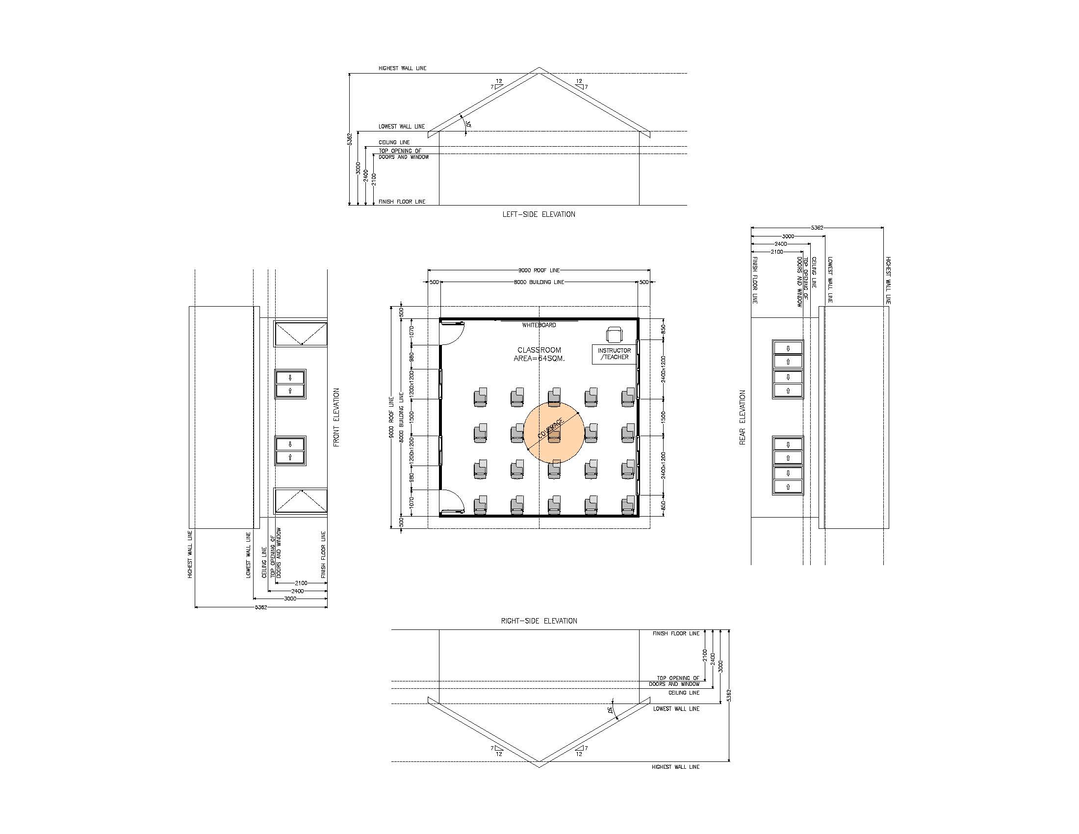
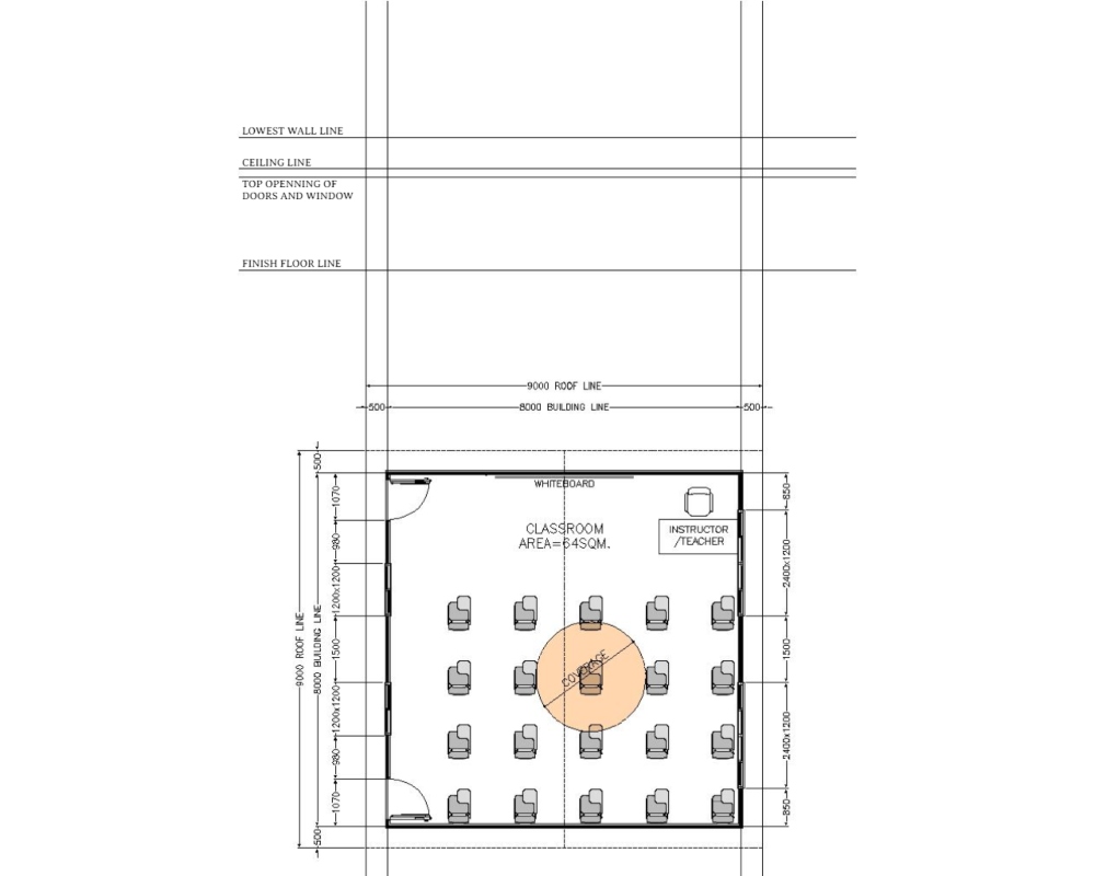
In order to create the elevation, we first must create a precise drawing plan.
Example:
Given Dimension: (Millimeters)
WIDTH: 8000
LENGHT: 8000
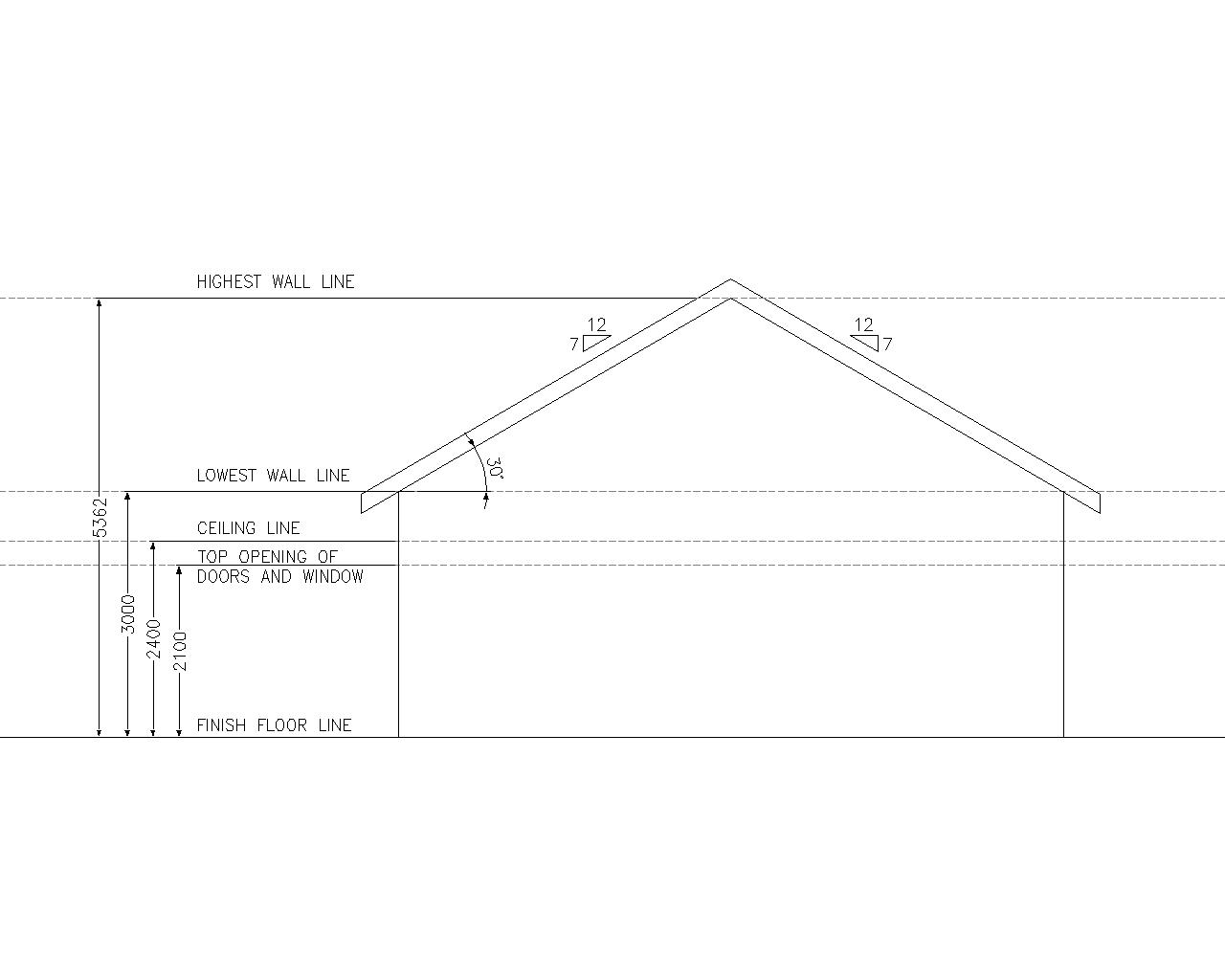
LOWEST WALL LINE: 3000
CEILING LINE: 2400
OPENNING OF DOORS & WINDOW: 2100
DOOR SIZE: 914(W)x2100(H)
WINDOW OPENNING: 1200(W)x1200(H) & 2400(W)x1200(H)
Roof Pitch: 30° or 7 : 12
Typically, we generate elevation views by simply specifying the measurement.
We will still be a little sluggish in producing the drawing this way, therefore we must discover another approach to execute the drawing precisely and quickly as possible.
How to create elevation views ?
The given dimension are all fully enumerated, rather than entering them one by one, let’s just establish a projection line from plan.
There were helpful commands in AutoCAD for addressing this task.
A. Ray Command
- it creates a line that starts at a point and continues to infinite (one side)
B. Construction Line
- it create a line of infinite length (both side)
LET’S BEGIN!!!
XL – XLINE (Construction Line)
Command: XL (ENTER)
Specify a point or [Hor/Ver/Ang/Bisect/Offset]: V (ENTER)
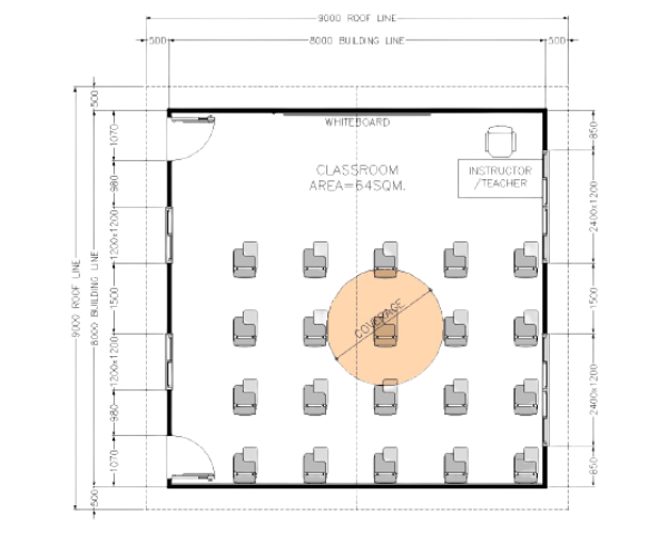
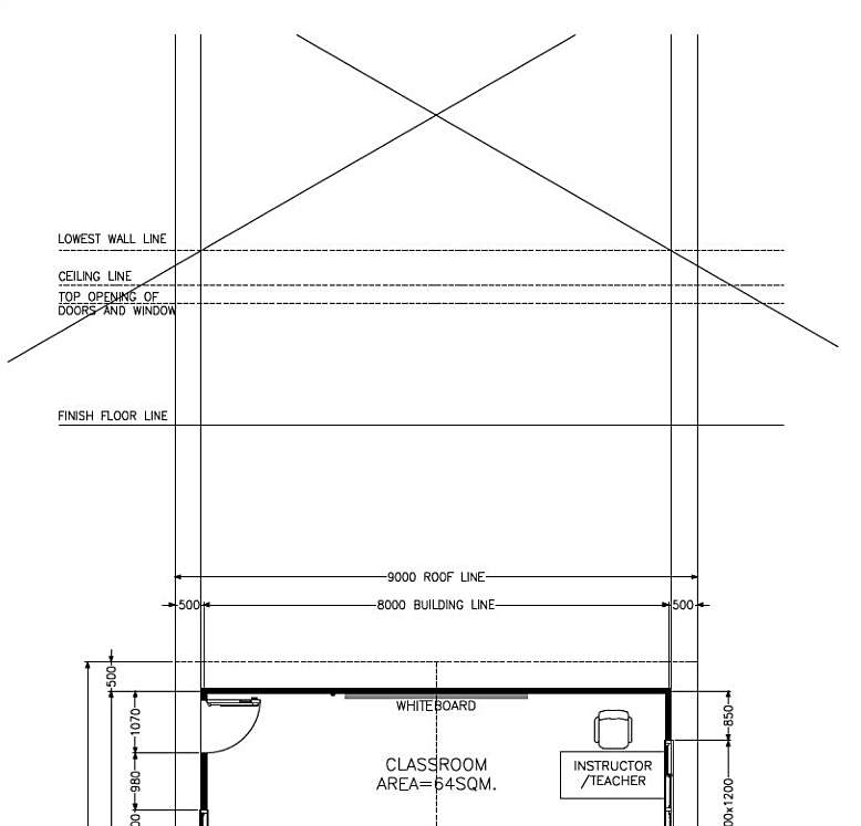
Using this vertical construction line, project our drawing vertically (Imagine the Side of the Building).
Specify the corresponding reference point: (By Clicking in the plan until we get the building boundaries as shown in the figure below)
Command: XL (ENTER)
Specify a point or [Hor/Ver/Ang/Bisect/Offset]: H (ENTER)
Command: CO (ENTER) Select objects: 1 found
Specify second point or [Array] : 2100 (ENTER) “This the door and window top opening”
Specify second point or [Array] : 2400 (ENTER) “This the ceiling line”
Specify second point or [Array] : 3000 (ENTER) “This is the Lowest wall Height”
Using this horizontal construction line (as shown in the figure beside). This will establish the building’s elevation (building Height)
Command: XL XLINE (ENTER)
Specify a point or [Hor/Ver/Ang/Bisect/Offset]: A (ENTER)
Enter angle of xline (0) or [Reference]: 30 (ENTER)
Specify a point: (Click on the intersection line of building line and building height.)
Mirror or repeat the step to create the other portion of roof.
Command: XL XLINE (ENTER)
Specify a point or [Hor/Ver/Ang/Bisect/Offset]: A (ENTER)
Enter angle of xline (0) or [Reference]: -30 (ENTER)
Specify a point: (Click on the intersection line of building line and building height.)
By now, you should be able to see the result side elevation displaying the roof pitch slope, and you should be free to set some thickness of roof around 200MM including the roof framing.
*REPEAT THE STEPS FOR OTHER ELEVATION*
To achieve and complete the elevation, use the appropriate commands such as copy, fillet, trim, hatch, and so on. (See above for output).