


Now Reading: Elevation & Section Drawing
- 01
Elevation & Section Drawing


This tutorial episode’s technique utilizes use of a construction line. In addition, basic drawing and modifying operations are managed. (previous lesson)
CREATING THE FRONT & REAR ELEVATION DRAWING
The simplest approach to create views is to project the visible component of the building. Start projecting the building’s columns; there’s no need to input the dimensions because they’re already available. Next, establish a finish ground line for your structure by drawing a horizontal line that intersects the vertical projected construction line. Then, offset the horizontal line by copying it and enter the required building height. Because the window opening and type are the same, project one window and replicate it to the other side of the elevation.
CREATING THE SIDE ELEVATION DRAWING
This second elevation would be considerably easier because we had already established the height of the structure. By horizontally projecting the side of the building design and rotating those projection lines, you’ll finish up with a vertical construction line. Then, from the previous elevation, draw a projection line to mimic the height of the structure. Make a few adjustments to complete the building’s side view.
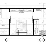
CREATING THE SECTION DRAWING
Creating a building section requires us to use our imaginations to design the inner components of the structure. Meanwhile, let’s make a cutting plane, showing the kitchenette area.